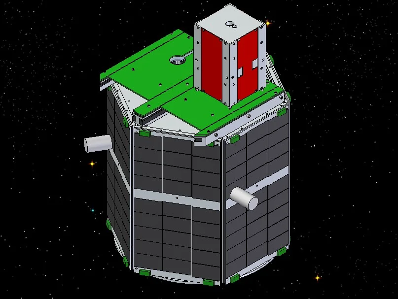


Akoya is a nanosatellite host spacecraft built on a generic bus hosting two Bandit proximity operation spacecraft. On orbit, The Bandit spacecraft are lifted out of their docks and the dock lids are closed behind them enabling charging with a circuit closed between the docking ball and dock face plate. Once fully charged, they can be deployed to autonomously navigate around and inspect Akoya. I worked on this project in various roles including ground software, flight software, and electronics design.
Bandit Electronics Redesign
Initial prototypes of Bandit leveraged analog cameras and ATmega128 8-bit micro-controllers. These were the same processors used for Akoya’s subsystems and were a lower memory variant of the processors later popularized in early versions of the Arduino UNO development platform. As development progressed it became apparent that it would not be possible to implement the necessary image processing and localization algorithms with this approach. I was tasked with finding a replacement solution and leading its development. We traded several more power processors and an FPGA based solution. After down selecting to an AVR32 based SoC and prototyping the FPGA based processing and localization algorithms, we made the final selection of the AVR32.


Overview
Bandit was sized to be a 2U cubesat with nearly 2/3 of the internal volume being occupied by the propulsion system. This left very little space for the control and communications electronics. In order to enable determination of Bandit’s orientation from Akoya, we made the external walls of Bandit PCBs and placed LEDs with unique patterns on each wall. Chip antennas were also placed on these walls to improve RF coverage and reduce interference from the structure, propulsion system, and control electronics. The control electronics were designed as a stack of four PCBs as to provide enough surface area for all of the necessary elecronics. The boards are described in more detail and stack order from top to bottom below.
AVR32 Breakout
Provides the core computation for the inspector, this was shared with the payload adapter board in Akoya. It was the most complicated from a layout perspective, utilizing 6 layers and contained the AVR32, SRAM, DRAM, and ROM. The connectors received the processor power supply and exposed the GPIO and other communication buses from the AVR32.
Communication/Storage/Imaging
Provides a 2.4GHz ZigBee radio, CMOS image sensor, SD card, and SoC power regulation (1.8V/3.3V switching regulators).
Power
Provides 12V and 5V switching regulators, battery management, and power polarity and static discharge protection.
Sensing/Actuation
Provides circuitry to control all of the solenoid valves for Bandits cold gas thrusters. For sensing, it provides a 3-axis roll rate gyro, a single axis accelerometer, connectors for two additional single axis accelerometers aligned in the other axes, and various voltage and current sensing capabilities for diagnostics and charge detection/verification.
Side Walls
Four identical PCBs made up the sidewalls of Bandit. They have LEDs for use in the visual positioning algorithms.
Front Panel
The front panel PCB (the one pictured is pre-redesign) had LEDs, a 2.4GHz antenna, electrical hookups for charging, and holes for the camera and IR range finder.
Payload Adapter (Dock Support Board)
Unfortunately, I have been unable to find any pictures of the redesigned Dock Support board. It utilized the common AVR32 Breakout Board, provided the SoC power, dock motor control, and interface to the core bus.
Akoya
Akoya provides core power subsystems, ground communications, thermal management, and ADC. When supporting Bandit operations it provides a communication relay between the ground and Bandit and recharges Bandit’s much smaller batteries via its solar panels and charging plates on the dock. Akoya uses a distributed computing architecture connected over an I2C bus. Individual processors are used for communications, power control, ADC, and interfacing with Bandit.
Attitude Determination and Control
Akoya uses roll rate gyros, accelerometers, and a horizon finding system to determine its current orientation. It then uses magnetorquers to control spin and orientation.
Command and Data Handling
The comms system receives commands and transmits telemetry over a 500MHz data modem. The system periodically queries the other systems for updated telemetry over a shared I2C bus. It also re-transmits encapsulated commands received over the data radio through the I2C bus.
Ground Systems
Prior to working on the spacecraft, my first role was in the ground system. The team had a basic test console used to interact with the satellite over a dedicated test radio. I lead the development of a networked, multi-user/role command and control system. It was able to coordinate the use of ground stations located at multiple university sites for more frequent and/or longer duration contact windows. Individual users were able to be authenticated and authorized at an individual command level granularity. The system handled antenna tracking and RF communications storing data in a centralized database for live command and control and post-operation analysis. Individual operators or engineering support staff were able to configure individualized display panels for their particular use cases.