


Akoya and Bandit are proximity operation spacecraft. Akoya hosts two Bandits on launch. On orbit, The Bandit spacecraft lift out of their docks and are charged on the dock face plate. Once fully charged, they can be deployed to autonomously fly navigate around and inspect Akoya. I worked on this project is various roles.
Bandit
I led the redesign of the Bandit electronics. The Atmega based electronics were not capable of doing the image processing and navigation algorithms at the same time. We upgraded it to an AVR32 based SoC. This was a much more powerful 32 bit processor running at over 100 MHz. Priori to this chip, the GNC developers wrote the navigation algorithms in Java and the ported it to C. The AVR32 provided a native byte code interpreter mode. This allowed us to develop the algorithms once.


Electronics Redesign
The electronics were designed as a stack of four PCBs. The boards' functions from top to bottom are: AVR32 Breakout, Communication/Storage/Imaging, Power, and Sensing/Acutation.
AVR32 Breakout
The topmost contained the AVR32, RAM, ROM, and the support electronics for those chips. This PCB served as a breakout for the GPIO and other communication buses from the AVR32. Due the complexity of this board, it is 6 layers, whereas the rest are 4.
Communication/Storage/Imaging
This board provides has a 2.4GHz ZigBee radio, CMOS image sensor, and SD card. The radio and camera are on this board because it is close the front of Bandit where the antenna and viewing port for the camera are.
In addition to these primary functions, this board also provided 1.8V and 3.3V switching regulators. These voltages are needed by the breakout board and aren't used anywhere else.
Power
This board provides 12V and 5V switching regulators and battery charging circuitry.
Sensing/Acutation
This board provides circuitry to control all of the solenoid valves for Bandits cold gas thrusters. For sensing, it provides a 3-axis roll rate gyro, a single axis accelerometer, connectors for accelerometers in the other axes, and various voltage and current sensing capabilities for diagnostics and charge detection/verification.
Side Walls
Four identical PCBs made up the sidewalls of Bandit. They essentially only have LEDs for use in the visual positioning algorithms.
Front Panel
The front panel PCB (the one pictured is pre-redesign) had LEDs, a 2.4GHz antenna, electrical hookups for charging, and holes for the camera and IR range finder.
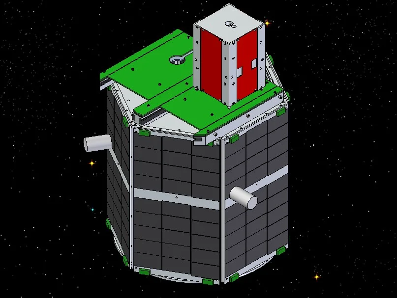
Akoya
Akoya is the host satellite. It carries two Bandits in a dock and deploys them on orbit. It acts as a communication relay between the ground and Bandit and recharges Bandit via its solar panels and charging plates on the dock. Akoya uses a distributed computing architecture. Individual processors are used for comms, guidance, and controlling Bandit.
Guidance Navigation and Control
Akoya uses roll rate gyros, accelerometers, and a horizon finding system to determine its current orientation. It then uses magnetorquers to control spin and orientation.
Command and Data Handling
The comms system receives commands and transmits telemetry over a 500MHz data modem. The system periodically queries the other systems for updated telemetry over a shared I2C bus. It also re-transmits encapsulated commands received over the data radio through the I2C bus.
Ground Systems
I also led the development of the ground system. We transitioned from a single console based system to a client/server architecture that allowed multiple consoles to subscribe to data updates from the vehicles and send commands two them.